Testing Clutch Drive Plate Production with NI Hardware & LabVIEW
- Apr 8, 2023
- 4 min read
Updated: Mar 27, 2024
*As Featured on NI.com
Original Authors: Paul Riley, Computer Controlled Solutions Limited
Edited by Cyth Systems
The Challenge
Creating an end-of-line test system to provide a traceable quality standard of clutch drive plates for supplying original equipment (OE) parts to the automotive industry.
The Solution
Using LabVIEW software and NI hardware, including the NI CompactRIO expansion chassis and associated modules, to configure and implement a test system that delivers accuracy, repeatability, high throughput, and reliability in the production environment.
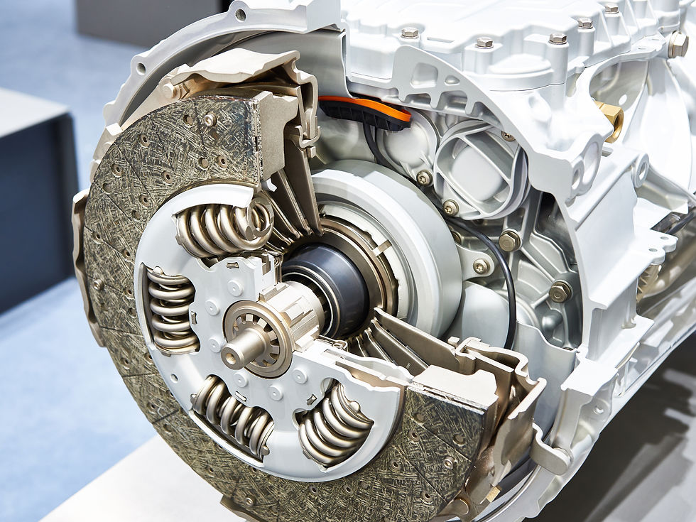
The drive plate component of a typical clutch transmits torque from the engine to the driveshaft. The component consists of a friction plate bound to a central spline with springs of varying stiffness. The springs absorb torsional vibration, which provides a solution for driveline noise, vibration, and harshness (NVH) problems.

cTo ensure this component works as specified, technicians have to test each one by rotating the central spline relative to the fixed friction plate and analyzing the spring rate and hysteresis characteristics to very fine tolerances.
System Hardware Overview
We based the system on a high-torque jig (800 Nm) and a low-torque jig (50 Nm) placed on each side of a floor-standing cabinet. Each jig uses a pneumatic actuator to clamp the drive plate, combined with a servo motor that provides a controlled angular deflection. We used a torque cell and encoder to acquire the hysteresis data.
The central cabinet contains the following control and acquisition electronics:
Intel dual-core Pentium 3.2 GHz processor
NI 7811R field-programmable gate array (FPGA) device
NI CompactRIO expansion chassis
NI quad-core strain gage module
NI 32-channel digital outputs (sourcing)
NI 32-channel digital inputs (sinking)
Baldor drives
The jigs contain the following hardware:
Baldor brushless servo motor
Alpha 220:1 gearboxes
Pneumatic actuators to clamp the parts
Applied Measurements torque cells
We needed to use hardware based on CompactRIO so we could develop a highly accurate machine within our budget. This gave us 24-bit resolution in the acquisition of the torque cell readings plus noise-free digital acquisition and angle control to a resolution of 0.0004 degrees.
Software Design
We wrote the complete software using NI LabVIEW software algorithms and the LabVIEW FPGA Module. Because the software was for a piece of production equipment, we included multiple features in our design. For example, with minimal operator computer use, the operator can simply load the part and press the start button after powering the system. Also, because our system uses encoders and does not require angle calibration, we built torque calibration into the software and hardware so we can check the torque readings against third-party load cells and displays. Then we can send these units for annual laboratory calibration.
With simple test accumulation, the supervisor can create or edit a test, thereby providing a library of tests for all drive plate variations. Also, we saved all of the resultant data in the well-structured and searchable NI DIAdem Technical Data Management Streaming (TDMS) format. This facilitates up to 800 tests per file per day with high-speed search capabilities using the XML-based parameter headers.
In addition, we designed the run screen to include historic traces of any measured parameter. This gives the operator/supervisor the ability to spot potential trends in the change of any result for predictive fault detection. We can also acquire data using FPGA hardware, which enables the acquisition of data against angle rather than time, providing a noise-free, ultrahigh resolution of data capture with no wasted data.
Using LabVIEW and Associated Hardware for Efficient Development
Several LabVIEW features were key in the smooth development cycle of this machine. With the LabVIEW 8.0 project environment, we can contain all PC code, subroutines, and input/output information in one place. We can also put all FPGA-related code, project documentation, data sheets, and specifications in one environment, making future servicing and maintenance easier.
Also, the CompactRIO digital input and output modules saved a complete level of intermediate wiring. Normally we convert the computer signals to/from 24 V for operating various solenoids and reading inputs via an intermediate rail of clip-on solid-state relays. Because we used CompactRIO 24 V-rated modules, we eliminated all of this wiring.
Using the CompactRIO strain gage module, we achieved a direct connection from the torque cells to the acquisition hardware, thus reducing wiring and minimizing noise. In the software, it provided simple calibration of the transducer with self-checking offset corrections down to a resolution of 100 fV.
With the FPGA architecture, we acquired data from each rig independently. This is normally difficult to achieve in a PC-based architecture and usually results in the extra expense of a second PC or a slower synchronous throughput of parts.
Furthermore, we used the FPGA for firmware high-speed trip monitoring. The FPGA monitors torque levels at a very high rate and directly cuts power if a level above 95 percent is reached. This saves on external analog hardware and has absolute deterministic response not achievable on a PC.
Original Authors:
Paul Riley, Computer Controlled Solutions Limited
Edited by Cyth Systems