
Industrial Flow Batteries Use Circaflex to Help Support the Power Grid
- Oct 14, 2022
- 4 min read
Updated: Sep 22, 2023

The Challenge
A designer and manufacturer of complex flow batteries approached us with the need for a system to control and monitor the function of their long-term energy storage devices.
The Solution
Using our embedded control system Circaflex paired with the NI Single-Board RIO we designed a system for the control and monitoring of flow battery cells in their proprietary energy storage devices.
The Story and The Cyth Process
Industrial flow batteries are batteries created to help support the power grid. They do so by charging and storing energy from the grid at high densities and then discharging energy later when needed. In doing so, these devices stabilize the electrical grid by providing power when production cannot meet demands.

System architecture diagram of a zinc bromide flow battery. (Credit: flowbatteryforum.com)
The customer, a producer of zinc-bromide flow batteries, approached us with the need for a system to control and monitor the function of their long-term energy storage devices. Zinc-bromide batteries are rechargeable and use a reaction between zinc metal, bromine, and an aqueous solution to produce an electric current. The liquid electrolyte presents an alternative to lithium-ion batteries that is less prone to overheating and/or fire. Each of these Zinc-bromide reactions is contained in a compact battery cell that requires an electronic controller. This is where the NI Single-Board RIO paired with our Circaflex control board excelled. The customer required a set of control boards that could handle high voltages, condition signals, and support high-speed communication. Using our Circaflex design framework were able to design this in a pair of boards tailored to the specific needs of their application enabling us to create a proof of concept within weeks.
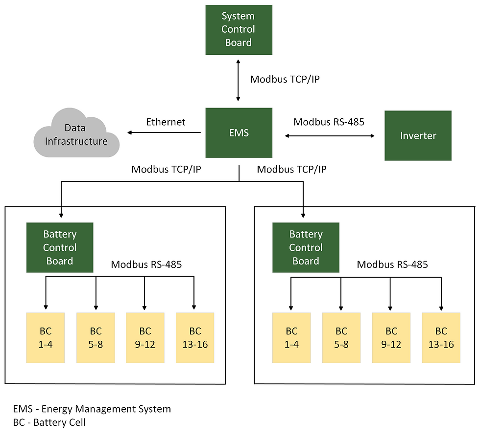
Our engineering team began by developing a Battery Control Board (BCB) that controlled and individually communicated with each of the 16 flow cells that made up the unit’s battery. Through wired connections, our board effectively monitored each of the cell’s voltages, currents, performance, health, and temperatures. Since each of the customer’s energy storage units contained two of these large battery packs, a System Control Board (SCB) was required. This board continuously directed the unit’s BCBs to one of three modes: charging, idle, or discharging. Likewise, the SCB gives reports to a user interface on the system’s overall health status which operators use during maintenance and repair.

Overcoming the Obstacles
The largest obstacle our team faced in the design of the flow battery’s control boards, was designing the board-to-board communication without an electrical connection between them. Normally when data is sent or received on any circuit board, an electrical connection is a requirement. The customer’s boards presented two hurdles in this area as no two components on the board could have any electrical connection, and the boards couldn’t have any electrical connection between each other as well. This was due to the high-voltage nature of the customer’s system. Each of the system’s zinc bromide batteries totaled 480V and if they weren’t isolated the voltage would short the boards and hence the entire system. Our team designed signal isolation into the battery control board so that each of the battery cell’s channels were isolated. This required an “air gap”, (additional space on the PCB) between channels. Likewise, for communication between the boards, our engineers found fiber-optic connectors to be the best solution. To enable communication between the SCB and BCB control boards, and between the BCB and battery cells, our engineers used Modbus TCP/IP communication protocols facilitated by a fiber optic design network. In doing so, our team was able to finalize the system of control boards needed to fulfill the high-speed communication requirements of the flow battery and was able to prepare the device for deployment.

Delivering the Outcome
Our engineering team designed a system of two boards to control and monitor zinc-bromide battery cells located in our customer’s energy storage device. The pairing of a battery control board and a system control board was the solution that best enabled high-speed communication, monitoring, and control of all the battery cells located in the customer’s unit. The Circaflex platform enabled our team to fast-track the design and development of our customizable circuit boards. If there was any ability that our board’s base design didn’t support, such as fiberoptic communication, we were able to add it using a custom module and connector. This allowed us to deliver a proof of concept within weeks and have the final boards ready for deployment within three months. We were able to help the customer accelerate the path to market of their industrial flow batteries while helping deliver a high-quality design that fit well within their project needs and deployment budget.
Technical Specifications
Battery Control Board
16 x Battery Voltage Analog In Channels, -5V to +15V
20 x SPDT Relays, 250 VAC,30 VDC, 8A
1 x Industrial Digital Out, 24V, 20 kHz PWM
2 x Industrial Digital In, 24V
1 x Fiber Optic, Transmit and Receive, 820 nm, ST
1 x GIGE
1 x CAN
1 x RS232 Serial Comm
1 x RS485 Serial Comm
1 x 24V Power Input
2 x O – 24mA Analog Current Output
3 x Thermistor Input
3 x 4 – 20mA Analog Current Input
System Control Board
1 x RS232 Serial Comm
1 x RS485 Serial Comm
5 x SPST Relays, 250 VAC,30 VDC, 8A
2 x Industrial Digital Output
5 x Isolated Industrial Digital In, 24V, 20 kHz PWM
2 x Industrial Digital Input
2 x Industrial Digital Out, 24V, 20 kHz PWM – used for Pulse Width Modulation
1 x Thermistor Input
1 x Fiber Optic, Transmit and Receive, 820 nm, ST
4 x Analog Out
3 x Industrial Analog Industrial Differential
3 x Industrial Analog Single Ended
Citation:
What Is a Flow Battery? – the International Flow Battery Forum. flowbatteryforum.com/what-is-a-flow-battery. Accessed 14 Oct. 2022.