Automating the Test of High-Current Circuit Breakers Using NI CompactRIO
- Apr 11, 2023
- 3 min read
Updated: Mar 27, 2024
*As Featured on NI.com
Original Authors: Xavi Salada, Techna International Ltd
Edited by Cyth Systems

The Challenge
Increasing the ease of mechanical and electrical testing of circuit breakers.
The Solution
Automating the safety test processes of testing circuit breakers by using pneumatics to test their mechanical operation and using high-accuracy sensor inputs/outputs to read the voltage status of the device’s electrical circuit.
Introduction
Circuit breakers are an essential safety feature of every building—key to preventing fires and protecting people and their belongings. Such devices must pass a number of safety tests before distribution. Electrical tests ensure the proper functionality of the device and mechanical tests guarantee the mechanisms can operate repeatedly for a long period of time. Completing these tasks manually is labor intensive and time consuming as tests are run in large quantities and can last for hours.
We needed an automated test machine to make it safer to test new products in the development stage and practical to test a large a quantity of devices during production. With this automatic system, an operator can control the test machine through a computer program instead of being in direct contact with the devices.


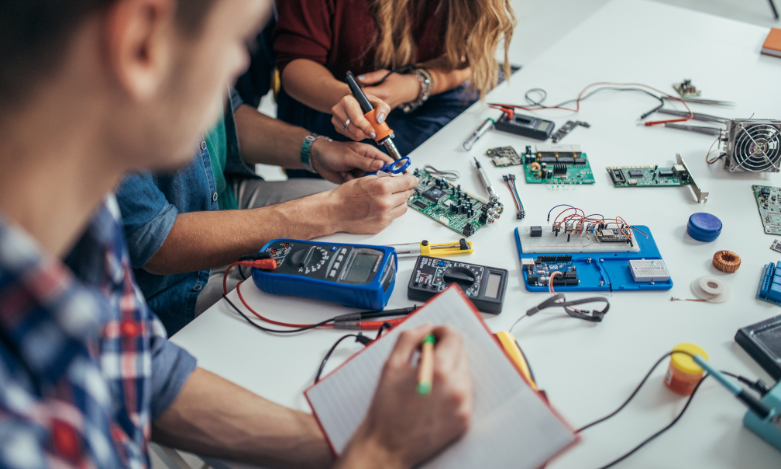
Left: Frame of automated circuit breaker testing system with DUT (Devices Under Test)
Right: NI cRIO-9063 & cRIO 9038 Controller Chassis
Application Overview
The test machine consists of two sections. The first section includes a pair of pneumatic pistons used to power cycle each unit under test (UUT) a number of times specified by the operator, as well as sensors to determine current levels and pin position. The second section has the UUT connected in parallel to a relay that acts as a bypass in case the device trips. A voltage sensor determines whether the UUT is still engaged or malfunctioning because of fatigue. LEDs indicate the test pass status for each power cycle. We repeat this schema using a programmable power supply to increase the number of devices that we can simultaneously test.
Running the test with the circuit breakers arranged in series runs the risk that some of the devices may trip due to heat generated by the amount of current passing through them. In this case the system needs to recover and activate the specific relay to bypass the tripped device so the test can continue. To do that, the program continuously scans all voltage sensors placed after each device to determine which UUT has tripped. When the program identifies the tripped UUT, it stops the power supply, activates the appropriate relay, and switches an LED to display this to an operator. The system then resets the power supply and the test continues. On the front panel, the operator can view the status of each UUT, the current used, and the remaining time for the test.
Control of the system, including the pistons, relays, LEDs, and binary sensors, requires a large number of digital inputs provided by the NI 9375 and USB-6509. We use the USB-6509 with MOSFETs for voltage regulation and the NI 9375 to serve as a 24 V source, which keeps our system design simple because we do not need extra circuitry. We connected a current clamp to the NI 9205 analogue input module using its 16 differential inputs for measuring the current levels passing through the UUTs.
Original Authors:
Xavi Salada, Techna International Ltd
Edited by Cyth Systems